
Samuel Clay is a grad student in the schools of design and of engineering at Harvard. He founded NewsBlur, a personal RSS news reader, and Turn Touch, beautiful control for the smart home.
Talk to him @samuelclay.
Samuel Clay is a grad student in the schools of design and of engineering at Harvard. He founded NewsBlur, a personal RSS news reader, and Turn Touch, beautiful control for the smart home.
Talk to him @samuelclay.
Back in 2014 I was driving up the 101 coming back from a YC alumni Demo Day and I had a lightbulb moment about the way I wanted to control my new Hue lightbulbs. That’s when the idea of Turn Touch was born. I’d had some experience building open source hardware projects for my home, and developing open source art installations for Burning Man at a slightly larger scale, but I had never thought I’d build an open source hardware project that would be commercially available (or at least available on Kickstarter). Turn Touch is now available to buy for $49 if you don’t feel like building your own.
There are four steps to building your very own Turn Touch:
Step one: Laying out the buttons and writing the firmware

Step two: Designing the remote to have perfect button clicks

Step three: CNC machining and fixturing to accurately cut wood

Step four: Inlaying the mother of pearl

Like many of you, I was one of those kids who took apart the stereos in my parent’s house to see how they worked. Since then I’ve been a full-stack engineer on most of my projects. Although I wasn’t quite sure how to build Turn Touch, I was committed to doing it, and learning how to build it from the ground up. At the Bay Area Maker Faire that year I stopped by the TechShop booth and signed up for one of their new member deals.
I build all my projects Open Source, so when I decided to start building Turn Touch I knew I wanted to document my process. My plan from the beginning was to release 100% of the knowledge, planning, and design behind Turn Touch as an open source project. Through building Turn Touch, I’ve learned what it takes to create not just one remote, but an entire manufacturing process. So that’s what I want to share with you in this series.
This is the full guide on how to make your own Turn Touch from scratch. This is the story of the design challenges faced when trying to make a seamless remote and how to overcome them. If you follow this guide, using the accompanying open source design files, then you will be able to build your own Turn Touch that you can use to control your smart devices and apps on your phone and computer.
Through open-source hardware like Turn Touch, I’m working to lower the barrier to entry when it comes to creating and manufacturing your own complex hardware devices. Sure, it’s not what you might call a “traditional business plan”. But I strongly believe that by helping other people use the same tools I use, our community of makers gets larger and more inventive.

At the end of the day, this isn’t a project devoted to turning a profit. It’s a project devoted to makers, wherever and whoever they are.
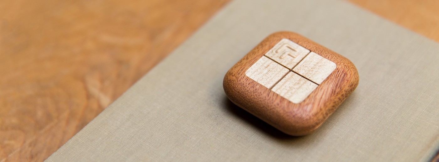
Pictured above and elsewhere in this series are all handmade prototypes. Turn Touch uses off-the-shelf components where it can, and only tools that are available to individual makers. No special tooling was required to build this remote. If you follow this blog series and use the included open source designs, you too can build a remote just like this.
I’ve broken this manual up into four sections. If you’ve done a bunch of machining my lessons may seem elementary, but the hardware part may be useful. If you’ve designed a bunch of hardware but have never worked with wood, hopefully this will lower your barrier to entry.
At the heart of Turn Touch lies a circuit board with four tactile switches and a bluetooth module. This board alone is the remote, since it can be used without a wooden enclosure.
The source code for the Bluetooth firmware, circuit board schematic, and board layout is available on Github.
The circuit board is composed of four parts:
 The Turn Touch circuit board
Choosing a Bluetooth radio isn’t trivial. In fact, choosing Bluetooth in the first place is a tradeoff.
The goal for the remote is to control smart devices, but those devices range in terms of which wireless protocol they speak. For the most part, you can assume WiFi is in the equation.
Philips Hue lightbulbs speak Zigbee, a low-power peer-to-peer mesh network, and connect to a hub that speaks both Zigbee and WiFi. Sonos speakers, Belkin Wemo smart power switches, Lockitron smart locks, and many others are also on WiFi.
So how about just using a WiFi module?
Part of the requirement for the remote is that a button press is near-instantaneous (with less than a 100 ms delay). But a WiFi module, such as the popular ESP8266, draws up to 250 mA at 3V (750 mW) when transmitting and as low as 0.9 mA when sleeping.
 Espressif ESP8266 WiFi module, $6.95 on Adafruit
Considering a standard CR2032 coin cell battery has 225 mAh, you can run a WiFi module with normal use (sleeping 99% of the time) for only 28 hours if you want instantaneous feedback. You can use bigger batteries, but now you’re working on integrating giant AA batteries into a tiny hand-held remote, which won’t work.
Better yet would be to bring the WiFi module down to the 10 µA level. But that requires a deep sleep which severs the connection. So when you press a button that requires the module to wakeup from deep sleep, it can takes several seconds to register the click. Amazon Dash buttons work this way and are able to last for over a year, since a several second latency is not a problem for them.
 Raytec MDBT40 Bluetooth LE module, $7.50 on Seeed
Your phone to the rescue
The good news is that while WiFi is too power hungry for this type of device, our phones and tablets, which are on WiFi and get charged every single day, work as a terrific relay. Our phones speak Bluetooth, so why not use the still fresh Bluetooth Low Energy (BTLE) protocol?
There are a number of usable Bluetooth 4.0 modules to choose from. There’s the BlueGiga BLE112 module, Roving Networks RN-42 module, BlueRadios BR-LE4.0-S2A module, and the famous Nordic Semiconductor nRF51822 based MBDT40 by Raytec (pictured above).
The principle concerns for a Bluetooth module are:
Here’s how the most well known and easily available Bluetooth 4.0 modules compare.

While all of the modules fit the necessarily small footprint, the MDBT40 module with Nordic’s nRF51 series won out due to the robust community and plentiful open source examples. It also had twice the max output power with half the power requirements of the BLE112. Plus it came with example projects for over-the-air device firmware updates (OTA DFU), which allows the remote to be easily upgraded for firmware changes down the road.
Not enough can be said about a thriving open source community around the nRF51 chip. Running into problems with power management, over-the-air device firmware updates, and even paramters for load capacitors on external crystals can be cleared up by consulting the massive online community that formed around the Nordic chip.
Now that a Bluetooth module has been chosen, let’s move on to the passive electronic components that it needs to operate.
The nRF51822 datasheet is solid. The standard GATT attributes of the Bluetooth stack is easy enough to implement. What we’re looking for in the datasheet are low power modes. The remote will be asleep for most of its life, but it needs the ability to wake up and transmit the button press in under 100 ms in order to be called instantaneous.
There are a couple options:
I chose the 1 year option. Interestingly, if I had chosen the 3–5 year option, the quickest way of waking up and transmitting a button press to a phone uses a special advertisement packet that can take up to 4 seconds to send and be read. These numbers are adjustable and there are certainly graphs you could draw, but I found the tradeoff to be worthwhile by staying connected and being limited to 12 months of battery life.
From the datasheet we see that the low power mode works best with a 32.768 kHz external crystal oscillator with 9 pF load capacitance and a ±20 ppm frequency tolerance. This Nordic Semiconductor support thread on minimizing current consumption has the details, and this thread can help you determine the crystal specs.
Apart from the external crystal used for low power, the only other peripheral we have on the microcontroller are the four buttons. These are internal pull-up GPIO pins with interrupts. This means that when the button is pressed in, the module is running at full power. One optimization to make would be to go back to sleep, but that would require external pull-up resistors, 1 per button, for a total of 4 more resistors on the board.
 The Turn Touch circuit schematic
Follow the rules and you get the schematic drawing above. I used EAGLE. Next time I would use KiCAD, if only because with open source EDA software it becomes easy to share the schematic and board layout with consultants and online forums for debugging and optimization.
You can download the board layout on Github.

 Top (left) and bottom (right) layout of the circuit board
Here’s where we get our first intersectional consideration. Before we were just thinking about what happens to the performance of the remote based on decisions made about the firmware and microcontroller. But the shape of the circuit board needs to know what the rest of the remote looks like.
The way I attacked this problem was to declare the minimum size for the circuit board and battery. A geometric symmetry is desired, but for the battery holder and the bluetooth module to fit, they had to be rotated 45°. From that requirement, tracks were routed around the five mounting holes. Two of the mounting holes are nudged a bit apart (the two in the top right) so that the board cannot be inserted upside down or in any other orientation on the same mounting pins.
The 8 magnets that hold the remote together look like they have bitten the PCB on all four sides. The reason for those divets is that the buttons themselves only take up so much space, considering their size is dictated not by electronics but by design. But the PCB is bigger than the button size as a matter of fitting both the battery holder and the bluetooth module. So we can cut into the board a bit with the magnets and just route the tracks around them.
Buttons come in many shapes and sizes to satisfy different requirements. I spent a lot of time looking at buttons that were industrial sized and could take pinball machine levels of abuse. Finding a way to press down and make contact was not trivial. Getting to “metal dome array” took a long, long time.
 Metal dome sticker arrays are custom yet inexpensive
The requirement for the remote was to have a low profile (short) button, but all of the mechanics of off the shelf buttons have a vertical profile of nearly a centimeter.

 E-Switch TL3315 Series (L) and Panasonic EVQ6P6 Series (R)
You can find surface mount tactile switches for $0.20 on Digikey. The E-Switch is one example. There are two reasons I did not choose to use this, one pragmatic and one aesthetic.
Practically speaking, if you have surface mount components on two sides of a board, you just doubled your PCBA (PCB assembly) costs, since the board house has to solder one side at a time, holding one of the sides down in order to solder the other side. It’s time consuming and costly, and if you can get away with a single-sided board, you should.
Aesthetically speaking, there’s this phenomenom I like to call “accidental swastika”.
 Whoops
By using a sticker dome array, we save money on PCBA but instead have to adhere the dome array during the full box build assembly process later on. Aligning a sticker array takes far less time, and we have the ability to choose between different click feels, pressures, and click sounds with tactile metal domes.
 Depth of field for a half-inch metal dome
Snaptron M-Series metal domes were the first dome I tried. It was magical. All I had to do was design the board layout with two concentric rings, add a via in the center as an escape for air, and tape the metal dome down.
 Taping metal domes with scotch tape on the left, custom made button array on the right
Ordering a metal dome array was easy. I just had to upload my gerber CAM files from EAGLE and send it off to CMD. $100 later I had 100 metal dome arrays with 400 individual buttons. Peeling them off and sticking them in the right spot is quick and accurate.
We now have a functional circuit board with a long-lived battery running Bluetooth. It’s now time to design the remote enclosure.
The source code for the CAD models is available on Github.

Now let’s put it all together. The remote is broken up into 7 stacked parts, starting at the top:
Starting the CAD process wasn’t easy. I didn’t even know which CAD program to use. I tried four programs, in order: Sketchup, Rhino, Solidworks, and finally Autodesk Inventor.
The models for Sketchup were limited by the simplistic capabilities of Sketchup, but Sketchup to its credit does a wonderful job of introducing you to the basics of CAD.
The models for Rhino were limited by the non-parametric capabilities of Rhino, where it was easy to model shapes but extremely difficult and time-consuming to change the parameters that determined how models affected each other.
The models for Solidworks were just the right balance of ease of creation and future modifiability. But once I tried Autodesk Inventor, its admittedly minor differences from Solidworks won me over. And while Autodesk’s Fusion 360 wasn’t production ready when I started the process, if I were to begin again today I was absolutely use it.
The question to consider when designing each of these layers is what is their relation to the layer immediately above and below itself. The circuit board defines where its mounting pegs are for aligning with the plastic insert below it, and it defines the button dome positions on top for aligning with the plastic button arms above.
 Seven layers: wood buttons, top wood case, top plastic insert, plastic button arms, circuit board, bottom plastic insert, bottom wood case
There’s quite a bit of overlap, so each of these pieces fit together nicely to form a much more compact package.
 2” wide × 2” deep × 0.68” tall (52mm × 52mm × 18mm)
The circuit board defines the most fundamental constraints, so the design must form around it. That’s not always the case, but when the device is trying to be as compact as possible, it’s a good place to start.
On the other hand we have the outer design, which is shaped to fit your hand. Those contours, while independent of the circuit board, are constrained to fit the circuit board footprint. So from the top constraints, inside and outside, we can begin dissecting the component layers and figuring out how to build this remote.
The button travels down the height of the metal dome when pressed, so there needs to be some way of holding the button in place while it’s pressed down so that it reliably returns to the original position.
 The actuator is tall enough to allow the button arms to bend without deformation
Below you can see the concept of buttons arms. Each button has two arms that angle out diagonally from the center of the button. This holds the button in place from the sides.
 The button array on the left attaches to the top enclosure on the right, held in place by its own structure
The remote has no border between buttons, so the button arms cannot cross over on top of other buttons. Two arms come from opposite corners and merge into the button half-way down its length.
Why not extend the arms all the way down to the center of the remote? Extending the arm would cut the deformation in half, since each part of the arm has half the height to travel when pressed. But it would also compromise the strength of the button, allowing it to break during assembly.
The length of the arms is a good compromise between strength and flexibility.

Possibly my favorite design inside the remote is how the buttons are held in place. Originally there were pegs in the insert and holes in the button arms. This worked but not well. It was at the mercy of various tolerances when building two separate plastic pieces: the top insert and the button arm. Any misalignment had to be corrected for on the other piece.
If the peg was too fat, the button arm’s hole had to be widened using a miniature, conic jeweler’s file. If the peg was too narrow, the button arm had to be adhered somehow to the peg to prevent it from slipping off. It was a nightmare.
By using tabs that reach over the top insert, the buttons hold themselves in place. During assembly the button array needs to be bent into place, but once attached it doesn’t go anywhere. This also solved the issue of broken pegs when buttons are forcefully pushed in during assembly.
Users are going to press a button on any part of the button. And if the press isn’t directly in the center, then it needs to be accommodated.
Each button is held in opposite diagonal corners, so when a button is pressed the arms deflect slightly downward. But they also form an axis that the button can rotate on.

If the button is pressed anywhere not on that axis of rotation, it will either push up the inside corner or outside corner and pull down the other side. To prevent this, we add a paddle on the outer corner of the button. This paddle is aligned with the plastic inserts so that it has a tiny bit of wiggle room but ultimately is constrained from moving up or down, preventing the button from rotating.
 The blue paddle rests between the bottom and top plastic inserts, preventing the button from rotating when pressed
During a demo this is everybody’s favorite part. The top and bottom of the remote need to be held together so that the end user can open up the remote and swap out the battery.
Most remotes use a plastic latch that either needs to be pinched by the user or pulled apart. Alternatively, some remotes are round and can be rotated around internal threads to open.


To solve this problem, I turned to a set of eight strong neodymium disc magnets. They get glued and placed into holes that are sized slightly smaller than the disc magnet, forcing the opening on the side of the hole to expand slightly. This holds the magnet in place and, coupled with an adhesive, ensures a strong hold on the magnet.
It is so satisfying to pull a remote apart and let it snap back together with the power of mangetism. And these magnets are strong, so they pack a lot more punch than anything else this size.
This problem has been one of the most perplexing and unforgiving issues I’ve come across on the remote. The issue is that the 7 separate pieces of the remote need to be adhered together in a way that compensates for the different relative tolerances and variable sizes of each component.


There are only a few sizes that must remain fixed. These are the circuit board, which has been fixed in size due to the requirements of the button positions. Second are the wood case’s top and bottom pieces need to be the same size and aligned perfectly with each other so that they form a seamless lip.
The trick is to have a buffer that can absorb the differences in tolerance between the two constraints. This buffer is between the inside of the wood and outside of the plastic insert. That space is apportioned to allow for inaccuracies that arise from two-sided machining.

What the above image shows is that the wood, on top, has a variable amount of space for the plastic insert to move around and align itself. The problem that arises during machining is that the top and bottom may not be evenly aligned, so the tolerance has to account for the maximum offset on one top and the maximum offset in the opposite direction on bottom.
While there is no issue with having a buffer that moves the button arms around, the buttons are no longer perfectly aligned with the opening in the top of the case. To account for this, the plastic button arms are inset from the edges, as evidenced by the purple circuit board peeking around the margins of the teal button arms below.
 Smaller button arms (teal) allow the wood to be independently aligned without overlapping other buttons
The wood buttons are glued on top of the plastic button arms, so they don’t need to be perfectly aligned. But the plastic arms are reduced in size so that a wood button isn’t sitting on top of two plastic arms that happen to be slightly offset due to any alignment issues.
But this brings up another issue. We want to maximize the amount of wood at every point while minimizing the total size. We do this because otherwise the wood could break in the thin sections during machining.
Let’s turn back to the see-through side view of the remote.

Notice the space by the yellow arrow is a weak spot that runs along the circumference of the remote. By minimizing the height of the plastic insert we can maximize the wood that holds it in. This minimizes the possibility of split wood during the machining process.
And with that we come to the most exciting part of the process, how to successfully machine the wood.
Now that we have our models, we need to figure out how to machine them out of wood. Workholding is the principle concern here. In order to consistently machine the wood on two sides, the wood needs to be held down. This is much harder than it sounds.
The source code for the CAM toolpaths explored below is available on Github.
 Lumber and machining fixtures line the entire wall in my office in SF
There are two central issues to consider: one is that each piece needs to be machined on both sides, and second is that the workpiece needs to be held down both facing up and facing down so that it can be machined on both sides. In our case, we want to scoop out the insides of the remote out to fit the circuit board and button arms while contour cutting the outsides of the remote to fit the desired shape.
Designing the CNC machine toolpaths to sculpt the contour of the case while pocketing out its insides, assuming the workpiece is held down, is not terribly difficult. There are only a few strategies that you need to use and they mostly involve answering the question of how fast to cut while maintaining as clean a cut as possible, which we’ll get to later.

Above, I’ve designed the fixture that gives us 15 pattern-matched remotes at a time from a single board of wood 24” long and 7” deep. That’s just about 1 board-foot (bf) of wood. A single board-foot costs anywhere from $5 to $50, with maple at $5/bf, mahogany at $10/bf, padauk at $15/bf, and rosewood at $40/bf.
The top half of the fixture is the inside of the remote, the bottom half is the outside of the remote. We’re machining both the top and the bottom next to each other at the same time because we want the wood to pattern match.

 Examples of pattern matching with mahogany on the left and padauk on the right
 Pattern-matched Rosewood halves come together beautifully to form a single remote
Since we want the top of the remote to match the bottom of the remote, they must be machined next to each other. Our fixture reflects this by placing a top half next to a bottom half, and always in the direction of the wood grain. That way when the top case is flipped over like a book and closes on the bottom case, the grain lines match up.
Let’s start with the first fixture design because it was simple and was designed to only make a single remote at a time.
 The first fixture that successfully machined a remote
This animated gif beautifully illustrates the basics of machining the remote on both sides. This design uses a vise clamp that will quickly prove to be haphazard and inaccurate.
Unfortunately, the truth is that using a vise clamp leads to needless suffering.
The hardest part about using a vise clamp is ensuring that the registration and orientation match when flipped upside down. Not only do points on the x, y, and z axes have to be the same, but they need to be the same all the way down the workpiece. Any accidental tilt, turn, or shift when flipping the wood blank over results in a mis-alignment, and when that shift is greater than the width of the wood, we’re left with a work piece that abruptly breaks during milling.
And to make matters worse, errors are doubled when the piece is flipped. A 0.005” shift (less than the height of a fingernail) is a proportionate shift in the other direction on the opposite side, resulting in breakage happening more often than such a slight shift would imply.
The good news is that it’s easy to design a better fixture. The vise clamp suffered from multiple issues. Having to hold down the vise clamp itself was problematic, as it could subtly shift during machining. There are constant orientation and registration issues with a vise clamp unless you are fortunate enough to have a CNC track that can securely hold down the clamp.
We can clean these issues up with a fixture cut into a ¾” plywood board.


 Nearly finished with buttons on the left and cases on the right, but still needs to be cut out and sanded down before finishing.
This is fundamentally the same fixture as the vise clamp with a few important differences. See those alignment pin holes in the top image? Those are going to be responsible for keeping our x and y axis consistent when the piece is flipped over. And the z axis is kept consistent with the use of a flat plywood board that is level to the CNC’s spoilboard.
Note that the fixture itself is not registered to the table, it’s simply attached with screws. So when we put a blank wood work piece down, we drill the alignment holes directly into the wood and into the fixture. When one side is completed, we flip the wood blank over and use dowel rods to ensure we’re still registered in the same spot.
So this fixture addresses alignment and orientation issues in all three axes, but because it is not itself registered to the table, we cannot reuse the registration holes, as the fixture is never going to be put into the exact same spot again next time it’s used.

More importantly, there are still tabs holding the wood remotes in place during machining. Tabs take time to machine around since you can’t just have your toolpath wrap continuously around the contours of the remote without stopping. The CNC machine now needs to pick itself up and climb over the tabs for each rotation around the remote.
Using tabs also means that the remotes cannot be placed right next to each other. There are these bars of unused and uncut wood between each half of the remote. These untouched bars allow the wood to be held down with clamps, since the remote isn’t sitting on anything. But they are a waste of wood!
 A belt sander once nearly ate through my fingernail from the top
And to top it off, once the tabs are cut with diagonal cutters and you pull the individual remote halves out of the larger workpiece, you have to manually sand down the tabs, which is error prone and dangerous.
Here’s where it gets interesting. In order to get rid of tabs, we have to figure out a way to hold down each individual remote as it is being machined.
The cutter is contouring around the outside border of the case, so there’s no way to hold the case from above without having it in the path of the cutting tool. Ideally we’d hold it from below, but that requires messy adhesives or a complicated locking system. And that brings us to vacuums.

Vacuum tables are outside our price range expensive, but we can build our own for the cost of plywood and glue. Above you can see that we’ve built a hollow box about 3” high. It’s just ¾” plywood cut into the shape of a box and glued tight. On top we’ve glued additional wood, which is then machined into the inverse of the remote.

Zooming in we see that the top case (left) is too thin to use a large hole. So we drill a few dozen 1/8” holes around the perimeter of the top case.
On the right we have the bottom case, which is solid in the center, so we can use a large 1/2” hole to have the vacuum hold it down in one spot.
You may also notice 5 metal alignment pins on each half. The vacuum holds the case down in the z axis, but the alignment pins are needed to hold the case down in the x and y axis as the wood is being machined.
 A cutaway that shows the alignment pins do their job
Above you can see how the 1/8” alignment pins handle the slight variance in the buffer between the case and the inverse fixture. They do a great job of holding the remote tight while it’s being worked over by the cutting tool. Before I used these alignment pins, oftentimes a case would become dislodged by the cutter, flinging it across the room.

The fixture itself sits on a spoilboard that is aligned to the machine, which allows for reuse of the fixture without having to recut anything. To pre-align the fixture, simply cut holes into your own spoilboard that sits on top of the machine’s spoilboard.
Use those holes as reference guides for the dowel rod that aligns the fixture to the spoilboard. You can see the dowel rods sticking out of the fixture and into the pre-drilled alignment holes at the bottom.
I’ve also cut out handles into the fixture, which makes carrying these heavy fixtures around much easier.
Just attach your vacuum hose to a $3 flanged inlet fitting attached to the side of the fixture. You’ll need to cut a hole out of the fixture. I used a $17 hole saw on a drill press to poke a hole for the vacuum to attach to.
 The vacuum fixture uses a standard Shopvac 2¾” hose
This is your standard 2½” hose, attached to an inexpensive ShopVac. You don’t need more than a couple horsepower to pull enough air to hold the wood down in place. This vacuum seal isn’t going to do anything for movement in the x and y direction, so if all it has to accomplish is offsetting the minor pull in the z direction due to vibration, then you won’t need an industrial pump or expensive vacuum to do the job.
In other words, it shouldn’t hurt when you place your hand over the hose and seal the vacuum.
 A beautiful rosewood workpiece being machined into five remotes
Because the fit is so tight, we need to add tiny ejection pockets underneath the wood case so we can wedge a lever in and pop the remote out. You can see this space at the bottom in the above photo.
You can see the secondary spoilboard on the button vacuum fixture, which follows the same principles as the case vacuum fixture. There are holes beneath each button, and three alignment pins holding the buttons in place as they are machined.


 Maple (center) being machined, Brazilian Satinwood (right) cut up into eight remotes worth of buttons
It’s important to keep as many tools and parts of the assembly off-the-shelf. There’s something to be said about being able to order more components and tools from a trusted vendor rather than having to source new custom tools. All of the tools used to machine Turn Touch are relatively inexpensive and will last you long enough to machine thousands of remotes.

The tools above are much of what I use in the wood shop. Starting with the milling and drilling bits, left to right:
Apart from the construction of the vacuum fixture, there’s many other lessons to learn from machining these remotes.
Figuring out the feeds and speeds for cutting into the wood
The feeds and speeds took a bit of trial-and-error but eventually I settled on values that meant an entire remote could be machined just under 10 minutes. With some changes to the cutting tools it is possible to bring that down further, but custom cutting tools cost on the order of $1,000. So the workholding fixtures we have here use off-the-shelf cutting tools, like flat end mills and ball end mills, which only cost $20 each.
My rule of thumb for mahogany is 120 inches per minute with no more than a 0.15” step down. For rosewood that number is cut in a third, so 40 ipm. Finding that number is simply a matter of running the machine and interactively increasing or decreasing the feeds until there is no chatter and the CNC machine sounds like it’s under control.


How do I know if I’m moving too quickly?
Apart from the horrible sounds of chatter, this may happen.
 I keep all of my broken cutters in a museum of mistakes
Different hardwoods need different cutting speeds
Some harder woods need to be machined at a slower speed than less dense woods. Rosewood needs its speeds cut into a third of what mahogany would use. Instead of having to update the toolpaths, I wrote this python script to automatically copy the mahogany toolpaths and cut the speed in a third and then re-save them as rosewood toolpaths.
The inverse fixture needs to compensate for differences in the wood
Below is a picture of what the fixture looks like without the wood on top. Notice that the fixture is red at parts. That denotes that the wood is about 0.005” inset. This means that there is a slight gap between the inverse fixture and the wood workpiece that will fit over it.
 The internals of the front three remotes without the wood
The reason for this slight gap is that if there is no gap then the workpiece will either not fit perfectly onto the fixture or it will get stuck, as it is holding the fixture on all faces. By adding a 0.005” gap between the two, they can better fit together. And the alignment pins and vacuum holes protect the wood from shifting around any axis, so the buffer could possibly even be bigger.
With that, we now have perfectly aligned wood pieces that are ready to be adhered together. All we have left is to inlay mother of pearl on the bottom of the remote to complete the process.
I set out to make the most beautiful remote I could. And after observing what many of the most beautiful handheld objects I’ve seen had in common, it became clear that Turn Touch deserves an inlay.
The source code for the inlay paths and laser cutter settings is available on Github.

The choice of mother of pearl came naturally. Wood and shell are both natural materials that are sustainably grown and can be beautiful to behold. The trouble with mother of pearl is that it is an exceptionally brittle material. Great care must be taken in both cutting the shell and then adhered it to the wood.

There are two main considerations to make when thinking about cutting the mother of pearl to fit. First is that the remote needs to be engraved to perfectly fit the mother of pearl. Second is that the mother of pearl itself needs to be cut to fit the engraved wood with no margin between the two.
 As thin as paper, this mother of pearl shell is only 0.007” thick.
Let’s begin with how I started the engraving process. The wood is considered the source of truth and will be engraved with no compensation for the mother of pearl. The shell must compensate for the wood.
Originally I used the ShopBot CNC machine to engrave the logo into the wood using a 1/32” flat end mill. There were a few issues with using the CNC to engrave:

Worst of all, due to differences between machines, the laser cut mother of pearl would have slightly different dimensions from the CNC engraved wood in both the x and y axes, resulting in a not-quite-perfect fit, leaving a variable sized gap between the shell and the wood.
 There’s an unfortunate margin between the engraved wood and the cut shell
The fix is to use the same machine for both engraving and cutting so that the same machine tolerances are applied, resulting in a uniform offset between wood and shell.
Engraving on a laser cutter is very different than engraving on a CNC machine. Whereas a CNC will route a tool bit in a pocket, stepping over itself with a minimal amount as to be efficient as possible, a laser cutter will rasterize the pocket shape and work in a way not unlike a 3D printer: line by line.
Before we begin working with the laser cutter, we take simple safety steps to ensure our health. The first few times I worked on the laser cutter, after about an hour my throat started to hurt. Probably due to all the acrylic being massacred by other people sharing the pool of laser cutters.
Wear gloves and wear a dust mask. Your lungs, skin, hair, and fingers will thank you.
 Nitrile gloves have no latex and are not coated in the messy dust that makes them easy to put on and remove
Here’s what we’re going for. We need to accurately engrave into the wood. This means that the cut needs to be centered and oriented. If we were to just place the remote bottom side up and shove it in the corner of the work bed, the engraving would come out askew.
 60W CO2 Universal laser cutter, sped up 40X for dramatic effect
Here we can see the laser cutter do its magic. To achieve this registration and orientation of the remote in the laser cutter, we need to do the same thing we did for the CNC machine: we make a fixture.
Lucky for us, this fixture is easy to make. I just took a ¼” piece of plywood and ran the laser cutter around the outline of the remote at full power to cut through. I had to adjust my offsets a bit to fit the remote, but it only took a couple tries.
 This fixture gives us perfect registration and orientation for the laser cutter to accurately hit the center of the remote
The remote is sitting inside this hole. Because the laser cutter made the hole, we can just center the logo engraving (or custom inlay engraving) in the hole to ensure that we are correctly registered. The plywood fixture itself is pushed up into the top right of the work bed so that it remains in a constant location.
The toughest thing about using a laser cutter to engrave wood is optimizing power settings. We want to perform the work as quickly as possible which ostensibly means using the highest power and fastest speed available. But we need to watch out, as too much power makes the wood burn.
There are three variables we can change: power, speed, and throughput. Power and speed are self-explanatory. Throughput is the density of the cut. Low throughput means that the laser cut spends longer making a higher resolution rasterized cut. So low throughput takes 3 minutes while high throughput takes only 15 seconds.
We want to start with establishing a minimum throughput that gives us the minimum acceptable quality of the cut we want but at the fastest speed possible. So we start with a low throughput to establish high quality and then move up in throughput until we reach a cut that’s too sparse.
Take a look below at this mahogany wood blank to see what happens when wood burns, even subtly. Starting on the right-hand side you can see how the laser cutter’s exhaust system pulls the smoke up and over the wood, leaving a burn scar above the cut.
 A mahogany wood blank worked right-to-left, the left-most engraving was chosen for its perfect height match with the shell
Starting from right to left:
YMMV on your particular laser system, but this is a good way of narrowing down values until hitting local maximas.
When a laser cutter cuts through material, the beam diffuses and creates a sloped edge. You can see how this edge can be a problem below.

When you try to inlay the shell later, these slopes will cause the edges of the shell to sit higher than the rest of the shell. It would be very easy to crack the shell if you press it in, since it can’t handle the stress of resting on the sloped edge.
One way to reduce the sloped edge is to adjust the focus of the laser. Even if you successfuly set the height of the focus, it still might be off by ±0.005”, which is half the height of the shell itself. So it makes sense, once you establish power, speed, and throughout settings, to also attempt a few cuts above and below your laser cutter’s established focal point, in 0.0025” increments, and see if the slope goes away with the adjustment.
Alternatively, since the slopes are only at the edges, you can perform additional cuts with the laser, feathering the inner edges, offset by enough distance so that the diffusion of the laser doesn’t show up outside the engraving.
This is what I do and it only takes a couple extra seconds to make a few cuts at the edges on one side. Sloped edges do not necessarily happen on every edge, since the grain of the wood can naturally reinforce an edge or make it harder for the laser to make a clean cut. So in my case I only had to feather one edge of the engraving to get the shell to fit perfectly. And because the cuts are inside the engraving, it doesn’t show and the shell fits in at the proper depth.
This is the good stuff. Mother of pearl is such a delicate material that it only needs a light power setting. The only variables I messed around with were power and speed, since vector cutting has no throughput component like the rasterized engraving in the wood above.
 Thin mother of pearl needs to be weighted down so it doesn’t get sucked into the exhaust fan
Let’s cut the inside edges of the design first. Just as you don’t want to paint yourself into a corner, you want to laser from the inside out. Otherwise your newly free-moving material may not stay in place for those inner cuts.
 Test every inset variation to minimize the space between wood engraving and cut shell. I settled on a 0.001” inset.
The Universal laser cutter I used allows you to set colors that applies an order to each cut. I also used a lower power setting for the outside edge cut. Since the entire square is easier to separate that the inner cut, a faster speed cut keeps the mother of pearl marginally connected so that the individual pieces don’t go flying as they get cut.
 Hot cutting action
I could have run the laser at a higher speed (at a higher power to compensate), but I kept it at a low speed to ensure a quality cut. If the wood engraving isn’t perfect, it matters less than if the shiny shell has rough corners that become a lot more noticeable.
Once you’ve got the two cut materials, the wood and the shell, you’ll need to get them to stick together. Since there’s no forces acting upon the inlay other than to reinforce it down into the engraving, we don’t need a messy epoxy or expensive shell glue to hold it in.
I tried many glues and settled on squeezable Extra Time Control super glue gel. The gel makes application easier, instead of being thin and runny. However, using off-the-shelf super glue (cyanoacrylate) without time control gave me only 5 seconds between application and drying. So placing the shell into the engraving was a one-shot deal, with the shell becoming permanently affixed to the wrong place if you didn’t nail its position the first time.


 Better to apply the glue to the shell than to the wood, less run-off on to the wood that way
 Place and wipe clean
Time control or not, it’s still super glue and it adheres within 15 seconds. But because it has time control, any excess glue easily wipes off the wood with a paper towel.
 2 minutes of lasering per remote, 30 seconds of glueing, and you get a finished remote
That’s it! That’s the last step. We now have a complete Turn Touch ready to ship to backers.
If you want to be one of those backers, head to Kickstarter and get your own Turn Touch.
This is a four part series on everything you need to build your own Turn Touch smart remote.
If you want to get your own, Turn Touch is now for sale for only $49.